Keyway Slot Dimensions
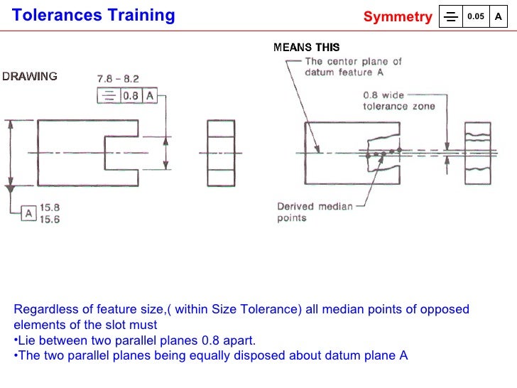
The method of dimensioning a parallel shaft is shown in Fig. 17.15, and a parallel hub in Fig. 17.16. Note that in each case it is essential to show the dimension to the bottom of the keyway measured across the diameter of the shaft and the bore of the hub. This practice cannot be used where either the shaft or hub is tapered, and Fig. 17.17 shows the method of dimensioning a keyway for a square or rectangular parallel key in a tapered shaft, where the keyway depth is shown from the outside edge of the shaft and is measured vertically into the bottom of the slot. Figure 17.18 shows a tapered hub with a parallel keyway where the dimension to the bottom of the slot is taken across the major diameter. A parallel hub utilizing a tapered key is also dimensioned across the major diameter, as indicated in Fig. 17.19.
WOODRUFF KEY DIMENSIONS ANSI Key No. 202 to 1012 Height Width Diameter Actual Length Full Radius Flat Bottom Distance Key Below Center No. Nominal Key Size W x D Min. In the English system, it is standard practice to dimension keyways. The hub keyway is dimensioned by its width and depth on the shaft – keyway sides. Referencing Figure 1, the keyway dimension is W x T 1.
Fig. 17.15 Keyway in parallel shaft
Fig. 17.15 Keyway in parallel shaft
- Fig. 17.16 Keyway in parallel hub
Fig. 17.17 Keyway for square or rectangular parallel key in tapered shaft
Fig. 17.18 Tapered hub with parallel keyway
Fig. 17.19 Parallel hub with tapered keyway
Fig. 17.18 Tapered hub with parallel keyway
Keyway Dimensions - Armstrong Metalcrafts
Fig. 17.19 Parallel hub with tapered keyway
Continue reading here: Worked examples in machine drawing

Was this article helpful?
Keyway Slot Dimensions Diagram
TolerancesDiameter Tolerance: Refer to Material Specifications page for tolerances for each material. All bars are checked with an insert bearing prior to shipment. Saw Cut Length Tolerance = +/- 1/16' (+/- 1/32' typical). Tighter tolerances available. Straightness Tolerance = .012' per foot, .006' typical. Straightness is not guaranteed.
*All keyways meet the ANSI B17.1-1967 (R1998) standard.
| Conveyor BeltingFlights / AttachmentsSprocketsTruKey® Shafting | |||||||||||||||||||||||||||||||||||||||||||||||||||||||||||||||||||||||||||||||||||||||||||||||||||||||||||||||